Entity relationship diagramming
An entity-relationship diagram, or ERD, is a chart that visually represents the relationship between database entities. ERDs model an organization’s data storage requirements with three main components: entities, attributes, and relationships. [1]
Definitions[edit]
These definitions are used gratefully from Dr. John Dalbey [2]
Entity[edit]
A data entity is anything real or abstract about which we want to store data. Entity types fall into five classes: roles, events, locations, tangible things or concepts. E.g. employee, payment, campus, book. Specific examples of an entity are called instances. E.g. the employee John Jones, Mary Smith's payment, etc.
Relationship[edit]
A data relationship is a natural association that exists between one or more entities. E.g. Employees process payments. Cardinality defines the number of occurrences of one entity for a single occurrence of the related entity. E.g. an employee may process many payments but might not process any payments depending on the nature of her job.
Attribute[edit]
A data attribute is a characteristic common to all or most instances of a particular entity. Synonyms include property, data element, field. E.g. Name, address, Employee Number, pay rate are all attributes of the entity employee. An attribute or combination of attributes that uniquely identifies one and only one instance of an entity is called a primary key or identifier. E.g. Employee Number is a primary key for Employee.
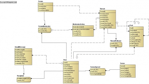
Example of a forum[edit]
This example is what an ERD MIGHT look like for an online discussion

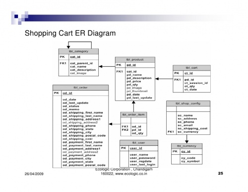
Example of an online shopping cart[edit]
This example is what an ERD MIGHT look like for an online shopping cart
